A Guide to the Setup and Operation
of the Very Large Scale
Synthesizer |
Genomic Technologies Inc. |
|
|||||
|
|||||
|
|||||
Index
Page
VLSS Validate Software Tutorial
System Diagnostics and Priming
10
During a Run
12
Appendix A
Appendix B
The Validate
Software which controls the VLSS is a graphically
controlled user interface. The software allows the user the
ability to edit and store an almost infinite number of sequences.
The software is designed to be customized by the user as they
become more accustomed to the system which further increases the
efficiency of the user interface.
The next section
is an introduction to the Validate software. The intent is to
detail the features of the system and to suggest ways of future
customization for your laboratories needs.
The software is
initiated by double clicking on the VLSS icon with the Genomic
Technologies group. The startup screen will appear as the
system loads into memory. Clicking on the startup screen will
reveal the VLSS Main Screen.
There are
several areas of the screen to take note of.
The set of
pull down menus at the top of the screen. These menus work
much the same as any pull down menus in a Windows application.
The menus give the user access to a variety of other screens that
can set default synthesis parameters, edit sequences, edit
synthesis protocols, and control valves within the VLSS. The
left hand side of the screen is reserved for status. The top
left status box shows what is going on for any loaded or running
column. The remaining boxes display a variety of status
information, which occur during a run. These areas are also used
for internal Debug information
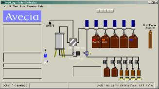
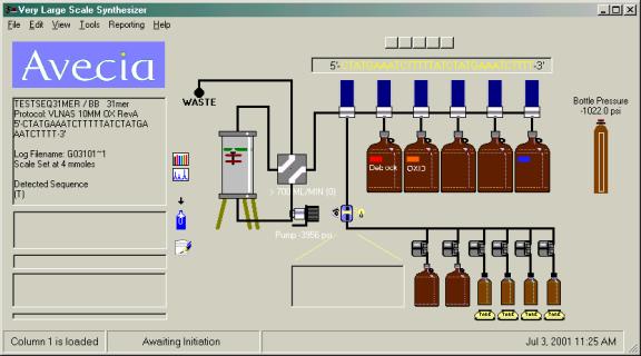
The right
hand side of the screen shows a representation of the VLSS
fluidic schematic. Clicking on the valve or pump images will
toggle between activated and deactivated states for these
components. The system can be operated in safe mode, which
prevents the user from accidentally clicking on a valve image and
activating or deactivating valve.
The system can be equipped with reagent scales. The value of the weigh on these scales can be viewed if the user moves the cursor over a bottle image assigned to a scale. The amount of fluid in the container is displayed in milliliters, providing the correct density for the reagent has been entered into the scales section under the program setup.
The pressure in
the bottle blanket system is displayed on the far right of the
screen. The fluid system pressure is displayed under the pump
image and this display will turn red during a run when the
pressure exceeds 30 PSI. This is not a fault condition, only a
warning. The system is capable of operating with specification as
long as the fluid pressure remains below 60PSI.
Setting Up
the Program
There are a
variety of parameters, which are user configurable through the
Program Setup. Access this tabbed dialog box by selecting FILE
from the main menu and slide down to Program Setup.
The initial
setup should involve typing in the Organization and user names.
Once the Organization or Company name is entered it is a good
idea to save the program setup and exit out of the Validate
software. This will allow the software to register the Company
name and then when you restart the software any optional features
which are specific to your software license can be installed.
Among the
several tabs in this program setup dialog, there are a variety of
program parameters which can be customized for your specific
needs. Most of these parameters are self explanatory. Hold the
pointer above any of the parameter settings to invoke a short
description of the feature. The default settings, in most cases,
will suit the average user. There is one setting which must
be changed in order to operate the synthesizer. This
setting is under the OPTIONS tab and is designated Run In
Simulation Mode. This parameter is set by default to
Simulation. It must be unchecked in order to operate any of the
valving or sensors of the system. It is set to simulation upon
installation to avoid a host of error messages which are
generated when the controlling computer is not connected to a
synthesizer. This also allows the user to install the software on
an office computer to practice with the software or edit
sequences or protocols from a remote computer.
 The user invokes the sequence editor by
either double clicking on the sequence editor icon in the Genomic
Technologies group or by using the pull down menus on the
VLSS Main Menu. Select EDIT and pull down to SEQUENCE.
The user invokes the sequence editor by
either double clicking on the sequence editor icon in the Genomic
Technologies group or by using the pull down menus on the
VLSS Main Menu. Select EDIT and pull down to SEQUENCE.
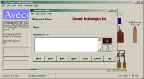
The sequence
editor is very simple to use. There are boxes for the user to
type the sequence name, client name and the actual sequence. The
client name is useful if your laboratory does any billing.
The sequence
files can be read by any standard editor program and are easily
imported to a variety of spreadsheet programs. The Genomic
Technologies Sequence Editor requires the user to name the
sequence. This is not the file name so the name is not limited to
eight characters. This is the name that will appear on the main
screen when the synthesis is running. When all the data is
entered, the user must save the sequence. Select save and a save
dialog box will appear. The default sequence directory is the SEQ
directory in the program directory, although the user can store
the sequence in any directory within the computer or any drive
located on a network if your computer is networked. Type the name
of the sequence. A date form of sequence naming can be useful for
laboratories that process many sequences. Press CR or
select exit or cancel to go back to the Sequence Editor and
continue editing additional sequences. If the user tries to exit
the Editor without saving the sequence a caution window will
appear indicating that the sequence should be saved.
The user can
only work on one sequence at a time and can choose New for
a blank template.
The Sequence
Editor is equipped with a Proof Reader. This feature is
useful for long sequences. The Proof Reader will speak through
the PC speaker although this sound not very good. A sound card
will enhance this feature quite dramatically.
The Sequence
Editor supports the full set of Cut, Copy and Paste
commands that come with most Windows applications.
Save your
sequence and exit.
In addition
there is a QUICK Sequence Editor selection under
the EDIT menu. This editor dialog is contained within the
Validate softeware and may offer a simpler interface for some
users. It has most of the basic functionality of the Genomic
Sequence Editor and does not require the user to jump out of the
main Validate software.
The Validate
Software can estimate the software consumption based on previous
synthesis’ consumption’s. The resources database file
is located in the database directory (Resources.mdb). This file
stores the reagent consumption per cycle for all reagents used
for each protocol. If new protocols are created or the edited and
a new name created for the protocol, this resource database needs
to be updated with the new reagent consumption information.
To prepare a
reagent consumption estimate, the user must first load a sequence.
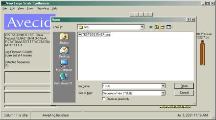 Double click the column image to invoke a
sequence load dialog box. Use the common Windows file dialog box
to locate the directory where the desired file is located. Select
the sequence from the directory listing by double clicking on it
or highlight it with a single click and press enter or click OK.
Next choose the protocol desired and finally the 5’ DMT
condition. These file directory locations will be remember the
next time you load a sequence and protocol for more efficient
loading.
Double click the column image to invoke a
sequence load dialog box. Use the common Windows file dialog box
to locate the directory where the desired file is located. Select
the sequence from the directory listing by double clicking on it
or highlight it with a single click and press enter or click OK.
Next choose the protocol desired and finally the 5’ DMT
condition. These file directory locations will be remember the
next time you load a sequence and protocol for more efficient
loading.
Another way to
load a sequence to a column position is by using the drag-and-drop
method. Open a Windows Explorer window. Use the Explorer window
to locate the directory with the sequence file then click on the
sequence you want and while holding down on the left mouse button
drag the sequence file over to the column location. Let go
of the mouse button. The protocol selection window should open
followed by the DMT condition box. Make these selections to
complete the sequence load.
Access the
resources screen by clicking on Resources under the TOOLS menu.
Now that a sequence is loaded, the estimated reagent consumptions
for the run can be calculated and displayed on this page. You can
print this page and use the information to prepare the reagents
and load the reagent reservoirs.
Prepare the
column reactor according to the appropriate SOP and install it
onto the synthesizer by connecting the column inlet and column
outlet fluid lines. It is advised that an inert fluid filter
be used before the column to avoid high pressure problems during
the synthesis.
The fluid
system is now ready to be tested for external leaks. Access the Column
Packing screen under the TOOLS menu. Use this screen to
initially make the system flow at 100ml/min with Acetonitrile.
Check the system for fluid leaks around the column. If there are
no leaks, or any initial leaks are corrected by tightening the
tube fittings or replacing leaky fittings, Use the buttons on
the left of the screen to ramp up the flow rate to the highest
flow rate used during the synthesis. Recheck for fluid leaks and
correct any if found. Stop the flow and close the Column Packing
window when this step is completed.
Access the Manual
Function screen under the TOOLS menu. This screen provides
access to several programmable macro functions. These macro
functions instruct the synthesis to perform a series of
mechanical operations to deliver fluid to or bypassing the column.
Disconnect the
column and pre-filter from the synthesizer and place the column
inlet tube into a waste container. Most priming macro functions
are, or can be made to bypass the column however it is safest to
disconnect the column just in case.
Select the
Prime Ancillary macro. This macro will pump a small amount of
each of the reagents to waste. Watch each reagent bottle to see
if the fluid does indeed move up the dip tube when the proper
bottle/reagent is being accessed as a visual confirmation. This
procedure can be repeated if the user desires a longer prime to
account for clearance of longer fluid lines.
Select the
Prime Monomers macro. This macro will pump a small amount of
each of the monomers to waste. Watch each monomer bottle to see
if the fluid does indeed move up the dip tube when the proper
bottle/monomer is being accessed as a visual confirmation. This
procedure can be repeated if the user desires a longer prime to
account for clearance of longer fluid lines.
These tests can be performed before or in
place of priming.
The system is
equipped with several programmable diagnostic procedures. These
procedure instruct the synthesizer to perform several mechanical
operations and access the scale readouts to monitor the
performance of the unit to determine if the system is operating
properly. The functions are located in the TOOLS menu under Internal
Diagnostics.
There are three
diagnostics which are suggested to be performed before every
synthesis.
Disconnect the
column from the system and connect a calibrated restriction line
which creates appropriate back-pressure for the column size being
used. Place the outlet of the line into a 5L waste container make
of polypropylene. Place the waste container onto the monomer A
Scale. It will be necessary to move the monomer scale from its
position on the monomer shelve to the floor. There is extra
length of wire to accommodate this rearrangement. Select the Pump
Flow Rate Test. This test will pump acetonitrile through the
system at varying flow rates and the scale will be accessed to
determine if the correct amount has been delivered. The results
will be displayed on the screen as the test proceeds and can be
printed when the test completes.
Reagent Flow
Rate test
Monomer Flow Rate test
Perform the
Reagent Flow Rate test and Monomer Flow Rate test in the same
manner. Alternatively the Monomer FR TST-Low Consumption can be
selected when it is desired to minimize monomer usage.
Remember to
reconnect the column once the diagnostics are completed.
The run is
initiated by clicking the start button (Arrow button) under the
column. The run may take several seconds to begin while each
reagent scale is accessed and the amount is recorded.
During a Run
The system will record the decrease in
weight of each reagent vessel for each cycle. These measurements
can be accessed under Reagent Consumption in the Reports
menu. It is advised to manually record the weights as the
synthesis proceeds and to also record the reagent consumption of
reagents such as Acetonitrile, which do not have scales. For
those reagent which have scales, the weights are read by moving
the mouse cursor over the particular bottle of interest.
During a run the cycle status is displayed
on the bottom status bar. The position in the sequence is also
noted at the top of the main screen. Yellow bases are those that
have been completed. Blue Flashing bases is the current base
position. The remaining bases are black.
It may be
necessary to top off a reagent when the reagent container is
insufficient to contain the required amount for the total
synthesis. The most appropriate time to top off is during the
first few moments of the cycle. At this point in the process the
previous cycle’s reagent consumptions have been accessed by
the scales and no consumption (Or very little) of the current
cycle has occurred.
If the system is
equipped with reagent scales for monitoring the reagent
consumption during the run additional steps should be performed
to re-tare the scales.
Access the Scale Management screen by selecting it from the tools menu. The current values measured by the scales for each reagent can be viewed by moving the mouse over each reagent container image. To tare a container, double click on the tare button below the image of the container. This procedure will record the current value being measured by the scale and use this value as a starting point for the current cycles reagent consumption calculation.
If this process is performed during the cycle and after a particular reagent was consumed then the reagent consumption calculation would yield a zero value for the cycles consumption of that reagent. Subsequent cycles would accurately be calculated because all the tare values are reassessed during the beginning of each cycle automatically. Alternatively, if this process of re-tarring is not performed then the current cycles consumption would result in a very large number for the reagent consumption. Subsequent cycles would accurately be calculated because all the tare values are reassessed during the beginning of each cycle automatically.
In addition, the
user should make a note of the reagent top-off in the synthesis
notation record.
The synthesis notation record is accessed
via the sketch page icon next to the column image. Right-click on
this image to add a note during the run. The note will be time-stamped
automatically. Alternatively the image can be left-clicked to
view all the notes recorded.
All the notes are saved to the database
under the run record.
Upon completion of the run, the column image will be changed and a double bar will now appear across the column.
Post synthesis
procedures, such as a T-butyl amine wash, can now be performed.
It is advised
that the monomer vessels be emptied and filled with dry
acetonitrile and a monomer prime procedure be performed to clean
the fluid lines. Disconnect the column during these prime
procedures.
Perform a Pump
Flow Rate Test as done in the pre synthesis procedure, to confirm
proper operation.
Print out a
synthesis report and trityl report(if installed) for
documentation and include these with the run documents.
Work up the
column reactor as prescribed by the appropriate SOP.
Reporting
The Validate
software contains a variety of reporting functions. Your software
license may include additional reporting functions. The basic
functions are described below.
Under the Reporting menu selection you will find
Print Report for Loaded Column
Print Report for Archived Run
These reports
print out a synthesis report. The synthesis report contains
information about the sequence including sequence statistics such
as molecular weight and melting temperature. If a synthesis is
completed, the completion time is reported in the top section and
the run results such as reagent consumptions are printed at the
bottom.
If you synthesizer is equipped with a trityl monitor and trityl data was collected for a completed run then this menu selection can prepare a Trityl Report based on the stored data file. The data file is named based on a automatically named Run Index Number. The data file will have the “dat” extension and is contained with the “Data” subdirectory of the Validate program directory. The dialog should direct you to this data directory. Select the “DAT” file with the appropriate Run Index prefix.
As
mentioned the prefix is auto-generated during the start of the
run submission. It is based on a date code and is unique for each
synthesis. The prefix is shared by all files associated with the
run such as the log file “jbi” and job file “job”
as well as the notation file “txt”.
There is also a
Reagent Consumption selection under the Reports menu. This
selection displays a form with any accumulation consumption data
for the loaded sequence. There is a print button available on
this form and selecting this will print out a report containing
the consumption values for the loaded synthesis. To obtain
consumption values for a completed run, which is not still loaded
on the screen, select Print Report for Archived Run, which is
above this selection. The consumption data will be printed at the
bottom of the general synthesis report.
If your system
is equipped with a UV scanner, this selection will print out a UV
report.
The UV scanner
option allows the system to measure and save a chromatogram of
the effluent from a valve train. Scanning is enabled via the
protocol and many scans can be made during a cycle. The scans are
primary used to identify what monomer bases are being delivered
through the valve train.
This report
consists of a representative chromatogram collected during each
cycle in the synthesis as well as the standard chromatogram set.
There are
several miscellaneous reports that you will find throughout the
Validate software. Primarily these reports provide a hard copy of
what is being displayed on the screen.
Macro Function
Resource Calculation
Debug Diagnostics
Logfile Viewer
The Logfile
viewer function is located under VIEW in the main menu. This
function allows the user to view a log file for any given run.
When selecting this function, the user is directed to choose an
individual logfile with the extension “jbi” and a
prefix which corresponds to a run index number described above.
Initially the
Logfile Viewer will display the full contents of the logfile.
Every functioned that is called during the run is recorded so
there are often a lot of entries in the logfile. It is usually
difficult to locate any specific entry. The Logfile Viewer
simplifies this process by allowing the user to select a certain
subset of logfile entries. A drop down box is provided with a
listing of common subsets the user might want displayed. Once a
subset is selected press the Select View button and the subset of
the logfile is displayed. The user is not limited to this common
listing. The user may type in any search string to create custom
subset listing. The Viewer will scan the entire logfile and
display only the lines containing the search string. For instance
if “Valve” is typed into the dropdown box then all
valve functions will be displayed. If there are more entries than
the display can show a slide arrow is available to page down the
list. To initiate a new subset select View All to display the
entire contents of the logfile. If you do not do this a subset of
a subset will be displayed.
A print button
is available for printing the subset.`
Appendix A
The protocol is divided into Cycles. The beginning of each cycle is designated by a two letter code “CD” followed on the same line by a single character designator (i.e. “A” or “C”) separated by at least one space. These single letter designators must be unique in the protocol. The end of each cycle is designated by the “CD” function of the subsequent cycle. Any Single letter designator including lower case letters can be used as cycle descriptors with the following exceptions (+,-,*,!)
+ (Plus Sign) This cycle designator is used by the system and is imbedded into the job script when the user chooses to have the process retain the final 5’ trityl protecting group.
- (Minus sign) This cycle designator is used by the system and is imbedded into the job script when the user chooses to have the process remove the final 5’ trityl protecting group.
* (asterisk) This cycle designator is used by the system and is embedded into the job script at the beginning of the process. It is used as a pre-synthesis cycle and is run only once during the process.
!
(Exclamation mark) This cycle designator is used by the system
and is executed by the system whenever an exception condition is
identified by an ongoing function. Primarily it would be
performed when a “WT” function, described later, is
being performed and certain performance levels are not achieved.
Usually this cycle is comprised of a reset all function “RS”
which turns off all circuits. Followed by several functions which
cleanse the reactor placing it in a safe condition. The cycle
terminates by executing a hold command for the particular column.
If this function is omitted in a protocol, the system will jump
to subsequent steps in the protocol when an exception condition
is encountered. A temporary message will be displayed and a
record of the event will be made to the synthesis log file
however the process will NOT go into a hold state.
The final line of the protocol is -
CD Blank Cycle needed to parse file DONT
ERASE THIS LINE!!!
Do not erase this line. It designates the end of the protocol.
Protocol Auto Scaling - Protocol Three
Letter Functions
A protocol can be made to autoscale. Autoscaling is a feature which automatically sets the scaling factors of the system. Scaling factors are normally set in the Program Setup. There are several predefined scales which can be chosen by the user.
If the system will be operating at a variety of scales the user may want to have the protocol set this scaling factor automatically to avoid a mistake.
The scaling factors effect the functions CV and MX. These functions are described in more detail below and include parameters which evaluate to column volume quantities. The scaling factor enables the system to calculate a volume in milliliters from the number of column volumes prescribed by the function in the protocol and the actual column volume set by the scaling factor.
To designate Autoscaling within the protocol, include a line, usually near the top of the protocol, as follows
PRO xx
Where PRO is a three-character function designator for auto scaling and where xx is a number (Integer value) designating the scale. The allowed numbers for predefined scales (in mmoles) are (1, 4, 5, 10, 20, 30, 40, 50).
The predefined scales assume a support
loading density of 25ml/mmole. This value is attained by assuming
a support molar loading of 90umole/gm and a support mass density
of 0.44gms/ml. If supports being used have significantly
different attributes from these values then predefined scales
should be avoided for selecting of scale values
To designate a non predefined scale, or actual scaling factor substitute the actual Column Volume in milliliters (integer values only) for the “xx” in the PRO line in the protocol. Usually this value will be above 100mls, and should always be above 50 to distinguish it from a predefined scale (i.e. PRO 100).
If however it is necessary that a scale
or column volume be defined within the predefined range (0-50),
this can be done as described above with the following exception.
In the event that a column volume is exactly equal to one of the
predefined scale numbers then you cannot use this value to define
an actual scaling factor. Instead use a value slightly higher
integer value. For instance instead of entering 40 enter 41 as
the actual scaling factor so that the system interprets this to
mean that the column volume is 41mls and not that the auto scale
is 40mmole and thus the column volume is 1000mls. Usually column
volumes are much higher then these predefined scale values.
Protocol Two Letter Functions
The following is a list of the protocol editor control codes and their descriptions. Each code begins with a unique 2-letter designation followed by several parameters separated by at least one space. The use of any other characters for delimiters, such as tabs should be avoided. The number of parameters is dependant on the particular code.
CD Cycle Designator Format {CD x} Where x is a single letter designation for the cycle
SC Sub Cycle Description Format {SC name} Where name is a description of the subcycle that follows.
The case where name is “Deblock” is special. This indicates the beginning of a cycle or cycle barrier. There should only be one occurrence of “SC Deblock” within the cycle. A special set of “Begin Cycle” operations are carried out, for example the polling of scales to determine the previous cycles reagent consumption. In addition the Deblock subcycle is used as a marker to calculate the cycle position for displaying the Sequence on the main screen and the indication of the current cycle.
Other subcycle definitions including Deblock, Coupling and End_Cycle are used as breakpoint positions. Breakpoints can be set for future cycles in the process. The specific point in the cycle for the breakpoint or hold operation can be further specified as before the Deblock, before the Coupling step or Before the End_Cycle operations. The positions at which these subcycle declarations will determine where the process goes into a hold.
AU
Audible function Format {AU “filename”} Where filename
is a filename of a WAV file located in the program directory. The
function plays the wave file without any delay in the run
AP Audible Pause Format {AP “filename” “Message”} Where filename is a filename of a WAV file located in the program directory. The function plays the wave file and then pauses the run. If the Message field is included a window will be displayed with the message.
EJ
End Job Format{EJ} used to designate the End of a run. Place this
function at the end of the post synthesis cycles usually
designated {+} or {-}.
WA
A Wait Step Format {WA xxxx} Where xxxx is the number of
milliseconds to suspend processing of the job script.
RS
RESET ALL. This function causes all circuits controlled by the
system to be deenergized. This function is used during a HALT
condition as well as during an exception controlled shutdown
process designated by the “!” Cycle
WT Wait Trityl Function. This function is used in conjunction with the inline UV spectrophotometer option. The function can be used in three modes, Set Wavelength mode, Integral mode and Threshold mode. If the third parameter is a comment or nonnumeric then the Set Wavelength mode is assumed. The absorbance at the wavelength designated by the second parameter is recorded by the system and stored in the History file.
If
the third parameter is numeric then the function operates as
essentially a wait step. The system will continue to function in
its current state until the parameters of the function are
achieved and the process can move to the next step in the
protocol. Typically this function is used during the Deblock step
to determine if enough trityl color as been eluted from the
reactor and that detritylation is complete. The Integral method
will wait for an accumulation of color whereas the Threshold
method is waiting for a maximum level to be reached and then a
subsequence minimum level. Which of these two method types is
distinguished by the sixth parameter. If this parameter is
a numeric type then it is assumed that the Threshold method is to
be used. Otherwise the Integral method would be assumed and this
sixth parameter would actually be a comment field for display on
the main screen during operation of the function.
The
following table lists the different usages of the parameters for
the methods described.
FF
FD
AB
AE
VF
Valve Function Format { VF xxxx Y
My_Message} Where xxxx is the valve map of the valve to be
controlled, and where y is the state (1 for on 0 for off) of the
valve and My_Message is a message that is displayed during the
operation of this function. Separate multiple words in the
message with underscores so that the line is parsed correctly.
This function takes virtually no time to perform so make note
that the message will be barely visible.
CV
Column Volume Function { CF xxxx My_Message} This is
essentially a wait step where by the wait time is determined by
the current flow rate set previously using the PF function and
xxxx is the number of column volumes in mls, delivered to the
column. My_Message is a message that is displayed during the
operation of this function. Separate multiple words in the
message with underscores so that the line is parsed correctly.
This function should be used exclusively for protocols that are
intended to be scalable.
MX
A Mix function Format {MX xxx yyy m a
b My_Message} This function delivers two reagents by
performing an inline mix actuating the valves designated by xxx
and yyy alternately. The “m” parameter represents the
number of discreet mixes. The “a” parameter represents
the column volumes of the reagent controlled by the xxx valve and
the “b” parameter represents the column volumes of the
reagent controlled by the yyy valve. The “a” and “b”
parameters are in mls. The function assumes a flow rate set by a
previous PF function. My_Message is a message that is displayed
during the operation of this function. Separate multiple words in
the message with underscores so that the line is parsed correctly.
This function should be used exclusively for protocols that are
intended to be scalable
MW
A Mix function the same as the MX function except with
parameters a and b the actual wait times are explicit and not
derived from Column volume amounts. Parameters a and b are in
thousandths of a second so an amount like 2000 would represent 2
seconds.
A up to date
listing of parts can be obtained from Genomic@Genomictechnologies.com